 |
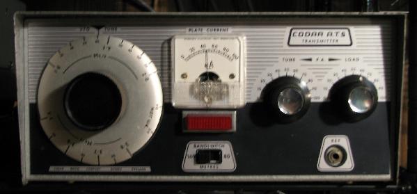
Tiny (as valve gear goes) at about 3 1/2" x 5" x 8 1/2", the Codar AT5 was what one today would describe as a QRP transmitter of about 10W for topband and 80m., built by Codar in England, and was popular in the UK in the mid 1960's.
Alright, I admit it. It's the nostalgia thing. It got to me, and when I saw this transmitter up on E-bay, and in the US no less, the inner sixties drooling teenager threatened death-by-acne if I didn't get it. This is the same inner sixties schoolboy that drooled over E-type Jags and Emma Peel, too. The Codar AT5 acquisition, as opposed to the other possibilities, hopefully reflects the accumulated wisdom of the intervening years.
The AT5 was the commercial rig to which every kid in Britain starting on topband AM aspired. And in the sixties, topband is where one usually started, for a number of reasons. Firstly, there was a community - starting to slowly drift to 2m, maybe - but there was a community. The then power limit of 10W DC input was entirely doable, transmitters were simple and kitchen-table-able, the tech was sufficiently low that parts were readily available, the chances of success high and the effects of inadvertant electrocution likely limited to "Yowch!". Antennas were bits of wire. Yep, topband AM was where it was at. Few European countries had 160m allocations at that time (fish-fone, coastal stations and Loran 'A' still dominated the band) and ones first CW contact with a Czech station was considered a rite of passage. CW was - as is now - the primary DX mode, for what little DX as there was. Making it across the Atlantic was rarified stuff, and the sort of memory that ranks up there, like those of a first lover, pint, or car wreck. But first and foremost, topband AM was about whiling away hours chatting to friends. (For a further, wistful perhaps, flavour of topband in sixties England, there's more in "Topband: Over There, Back Then" at the bottom of this page.)
About the radio
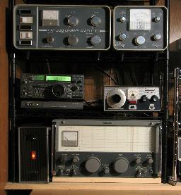 |
It's *so cute*!. It's really dinky, and it is remarkable even today that something functional and useful using tubes could come so small. The picture gives some clue to this with it sitting next to an Icom 735, itself a small radio.
It came with its matching PSU, (on its side, next to the big receiver) which is of similar footprint but slightly taller and significantly heavier, which conveniently also contains system transmit/receive/net switching.
Signal I/O is all on British style 'Belling Lee' TV coax connectors (which are quite unobtainable in the US) but which were very common on ham gear in the UK back then - even the very substantial bees-knees (and breathtakingly expensive at the time) Eddystone EA12 receiver had a TV coax connector for aerial. So amongst other things (like a set of the B9A plugs used for the interconnecting power lead) I had to order a bunch of these from England. A 6BW6, one of the power tubes, had met with a sad end during delivery, so a couple of those had to be sourced, too.
As with any electronics of that age (40+ years now) much renovation had to take place before it was wise to even turn the thing on: all electrolytic capacitors had to go bye-bye (thankfully there were no paper caps) and any out-of-tolerance resistors replaced as well. All that, combined with the fact that the construction of the set was - to be fair - pretty ropey with a startling number of dry joints, basically meant - hi-de-ho - rebuilding the PSU and transmitter almost completely. Renovation defined, really. Not a huge deal, since there isn't a huge deal in them.
Inside
The schematics and manual are available from that ever-fabulous resource for the anchorphile - BAMA..
In circuitry terms the AT5 is fairly straightforward. An EF80 pentode's cathode, control grid and screen grid act as a fairly unusual Vackar oscillator which works well (drift is not a problem) running on 160m.; the anode (from which the oscillator output is taken) is not included within the oscillator loop, so providing a measure of isolation and buffering. A second EF80 pentode acts as a power buffer on 160m. and as a doubler on 80m. A 6BW6 is the RF PA, which can pull some 50mA at 300V for a typical maximum of 15W DC input (50% over the then UK power limit - gasp!). RF power output on both bands is between 5 and 10W, depending on how the rig is loaded.
A 12AX7 acts as a two-stage mic amplifier with a gain tweak between them; there is tons of gain available - indeed more than enough for the recommended crystal microphone - and I can fully modulate this transmitter with a high-impedance dynamic mic. The single-ended audio output stage uses another 6BW6 in a rather clever Heising arrangement, described more fully later.
 |
For those not familiar with the 6BW6, it is essentially a 6V6 (baby 6L6) in a B9A enclosure - in other words it is a very robust valve, and in no danger of being abused in these circuits. It's a bit of a well-kept secret, being a superior tube in many respects (not the least in filament current, which at 450mA is a fraction of that of similar dissipation-class valves) to 'usual suspects' for this kind of application, such as the 12BY7, 5763 or 6BQ5 (EL84) or the B7G 6AQ5. The choice of such a strong valve for a mobile transmitter, where the load can be 'interesting' at times was wise.
A rear-panel switch allows the modulator to be de-powered and disconnected for CW; the available power to the RF PA notches up somewhat without the DC loss of the mod inductor. Keying is straight into the PA cathode - subtle.
Power Supply
 |
The accompanying power supply uses an EZ81 (a B9A full-wave rectifier valve, a souped-up EZ80) and an OA2 for the VFO regulator, and only has taps for 200, 220 and 240V AC on the transformer; to those with 230V dual-phase already knocking about for amplifiers and such this isn't an issue, but even if not, a small say 100VA autoformer to get up from normal 115V AC should suffice.
Initially I replaced the EZ81 with silicon rectifiers soldered to the back its socket, until I then measured the resulting HT; 350V is a bit cringe-worthy; the 300V-ish with the EZ81 is much saner.
Neat Features
As just said, there's not a lot to the AT5. As with many tube designs it is minimalist, but there are a number of really, and I mean admirably, clever design features:
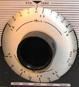
* Firstly, the VFO dial itself. Remember, this is a dual-band transmitter, 160 and 80. The fact it has a common VFO for the two bands, with 80 simply a doubling, is not the clever part: the large, circular dial has both bands' frequencies printed on it, 180 degrees apart. Turning the VFO dial all the way around until the correct band is indicated (the VFO capacitor being free to rotate continuously) makes for a very clean presentation.
* The VFO itself is a 'Vackar' variant which for only a part or two more gives noticably superior stability to a more conventional Hartley or Colpitts. I know, I've built a few.
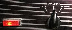
* The power supply neon is - for the worthwhile price of an additional couple of resistors and a cap - part of a relaxation oscillator, which serves to indicate when the the power is simply on by blinking or if the system is in 'Net' or 'Transmit" by coming on solid.
* By wiring up the power supply lead in different fashions, the filaments may be run at either 12.6V for, say, mobile (and the transmitter really is small enough to easily countenance mobile) or, as is normal with the PSU, 6.3V.
* The modified Heising modulation scheme is brilliant: A conventional Heising uses a single choke reactor common to the class-A modulator tube's anode and the RF power stage; the AT5 uses a centre-tapped choke - HT is applied to the centre-tap, the modulator is fed from one end, the RF PA from the other. In this way the standing current of the class-A modulator tube and that of the PA tube substantially cancel, as far as DC in the core of the choke is concerned. Since the choke has less DC to cope with, far cleaner modulation can be achieved for a similar-sized modulation reactor. Or, as in this case, a smaller choke can be used for equivalent modulation...
* A simple capacitor-coupled neon gives a surprisingly accurate front-panel indication of when the modulation starts to get non-linear. (This guy liked neons. Mind you, there weren't that many options back then.)
The Pi-Tank
On the down side, the output pi-tank was originally unswitched and one and the same for both 160 and 80, which means it was a compromise for both (mostly at the expense of 80) and definitely not optimum for either. A common modification (and apparently standard in later production) overcomes this with using spare contacts on the band slidey-switch to reduce the inductance for 80m. But that one-size-fits-all pi-tank is really the only really cheesy thing about the original design. Impressive.
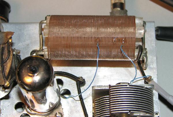
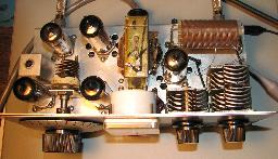
AT5 Pi-Tank - note tap points for 80 (L) and 160 (R).
The pi-tank limitation I addressed by extending the common modification somewhat, and spending some time optimising the pi-tank for the extremes (low end of 160, top end of 80). As can be seen in the picture, there is too much 'L' overall on 160m. (blue wire near right end shorts out the surplus) whilst 80m. needs significantly less inductance (blue tap near centre). A 680pF additional loading capacitor is switched in for 160m., too: The overall effect is now that the pi-tank has a sane 'Q' on both bands, the transmitter operates reasonably efficiently over all of both bands, and neither the tuning nor loading controls end up pegged one way or the other to achieve this into a 50 ohm load.
About Heising Modulation
Let's face it - there are very good reasons there are more complex modulation schemes than the Heising, even slightly elaborated versions such as the AT5's. Modulation depth, primarily. Even a prima facie thought-experiment is enough to show that a single class-A modulator tube by itself without transformation is not going to bang the PA volts around linearly between zero and times-two, when the best linear max-to-min excursion of which the modulator amplifier itself is capable is maybe half that. Sure enough, in line with most Heising implementations, the AT5 does 50% modulation quite linearly, and at a pinch (I'd only allow transients to hit this region though) maybe 70% at mid-band frequencies. Sufficiently over-driven, the modulation WILL get to break carrier, at the same time positive mod gets very angry-looking; I'm sure that so driven this could sound 'rather special' on-air.
The limitations of the small modulation choke exhibit themselves in fairly predictable fashion at both the low end (phase-shift 'tilt', core saturation) and high-end (frequency response, phase shift). Which illuminates a rather amusing paradox: to do proper audio pre-processing to maximize the limited modulation capability of this really simple little box would be far more complex than that for a for-real full-tilt-boogie broadcast transmitter! No, this .little box will not win any loudness wars, but it's about as much fun as an adult can legally have with five valves!
Topband: Over There, Back Then.
Back in the sixties in the UK we had 1800 - 2000 kilocycles (!) but big chunks of it were unusable, especially at night. Loran sat centered at 1950kc/s, and spread from about 1925 to 1975kc/s, day and night. There were (at least) two chains operating there, since we could hear their pulse-trains overlapping and phasing over a 30-second period or so - it sounded reminiscent of the phasing effect used extensively on '60's pop records. At night other chains centered at 1850kHz became audible, and we fancied that these were US or Canadian chains, but deep in our hearts knew they were just coming from the top end of Scotland or somewhere equally prosaic. (Just recently I found out they actually were from the other side of the Atlantic!) And then of course there were the coastal stations, many of which had base channels in the band. We could hear the southerners during the day: Lands End Radio (Cornwall), North Foreland Radio (Kent), but especially the closest - Niton Radio (on the Isle of Wight). The job description for a Post Office coastal station operator must have had something in it along the lines of "Must exude boredom for untold hours". Scheveningen Radio in Holland thundered in continually, too. (I later had reason to bless them dearly from the bottom of a very wet and terrified heart, but that's a whole other story). Interspersed were their calling channels, where the "fish-fone" folks (trawlers and such) would call in, or just set up shop and gossip with each other. Unwittingly calling "CQ" on one of these channels (or worse yet, one of the coastals' base channels) could result in a very stiff talking-to; my cheeks still flush thinking about the dressing-down I got from Niton once. On the cheery side, at least it meant one was getting out OK!
Clustered around 1900kc/s were "The Bells". These were the rythmic "bee-boo-boo-boop" "mas-ter-slave-slave" chiming of Decca "Hi-Fix" chains, pretty accurate hyperbolic navigation systems. It was being used extensively in the North Sea then in the early days of the oil and gas-field exploitation, estuaries, and elsewhere.
So as is becoming clear, choices of useful operating frequencies were quite limited. The daftly low 10W input power level didn't help, and it was obvious that we hambones were intended to be kept 20dB-odd below the 'real' occupants, lest we forgot what 'Secondary User' meant.
At night, as well as the second rash of Loran, coastals such as Cullercoats Radio (Newcastle), Humber Radio and even Wick Radio way up at the top of Scotland added to the minefield. But our fleapower AM could easily roll up and down the entire country - man, that was living large! (OK - so it's a small country...) Pleasantly, quite a few of The Big Signals of note at the time are still around: Mike G3SED down in Portsmouth used to have an astoundingly (suspiciously?) huge signal; I can still remember the plum tones of "G3JMJ, Edenbridge, Kent", and of course G3FPQ. We peons merely bobbed around in their wakes. Weekend mornings local roundtable chats were the norm; Tony G3WRF was the loudest local, with a 70' high cage dipole (*really* big-time for England), Eric G3PGM - a super-nice guy with a surprising history, Norman ("The Colonel, OBE") G5HZ, for whose TVI I often got blamed, Dave Morgan G3MEM (a trombonist jazz-band leader), Pete G3PWU, G3XOW, and G8KG over in Sonning.
Peppard, my home village, was intertwined with hundreds of acres of picturesque 'common land' - think wild park - which to us local kids' bemusement overran with frolicking townies of a nice weekend. 'Top Common', home to a couple of the local pubs, crested a ridge of the Chiltern Hills, and on reflection it wasn't to be unexpected that topband mobileers would deem it a great place to play, too. Hearing them on-air, I'd bike frantically over there up and down a couple of not inconsiderable hills, and so gaspingly met Bob, G3EJA/M, and G3TRY/M, and a couple of others. Yes, indeed - 'TRY was using an AT5...
My first topband AM transmitter had at heart an astonishingly Heath-Robinson-esque RF chain given me by Pete, G3NBU, one of my amazingly friendly and generous locals. The VFO (which dated to pre-war!) came from Stan Cook G5XB who lived just up the road in Gallowstree Common, and the lethal lash-up was modulated by a Leak TL12+ hifi amplifier 'liberated' from my Dad. It worked just fine, better than many. But, like other kid hams at the time, my spotty visage was turned by the promised wonders of a for-real shiny commercial transmitter: The Codar AT5, advertised on the back page of "Practical Wireless" for the princely (and as-good-as-million-dollar remotely) sum of Nineteen Pounds, Nineteen Shillings and Sixpence. Paper-round money being what it was I never did get one.
'Til now. Got a bigger paper round.

© Steve Dove, W3EEE, 2007