| Evaluating Receive Antennas with a Soundcard |
Introduction / Summary
Section (1) . . *** Receive Antennas ***
Section (2) . . Signals, and Signal Processing
Section (3) . . Measuring
Section (4) . . Problems and Solutions
First Introductory Subject - directional receive antennas!
|
Then along came NEC-based antenna computer modelling software, with feverish beavering in many a shack, affording a rash of promising new antenna designs. Schisms between those who swore by computer modelling and those who swear at it, and between those whose antennas worked and those whose never seemed to, grew deep and wide. What has been missing has been an independent way of measuring actual real-world antennas, in order to help defuse the polarisation.
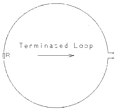
Nearly all the newly re-invented compact receive antennas derive from the terminated loop, the earliest reference to which I've found was in an appallingly mimeographed prewar training manual of my Dad's, transcribed as Fig.1. It was in the form of a circular loop with a feedpoint one side and a terminating resistor the other. It is cardioid (literally, 'heart-like') in azimuthal response, and very broadband, maintaining its directivity over many octaves. It was mentioned in the context of the far better known technique of summing a conventional loop's output (figure-8 response) with that of a co-located vertical 'sense' antenna (omni) to achieve a cardioid response.
In the terminated loop, if the termination is zero (shorted) then the loop acts as, well, a loop with its well-known figure-8 response; if the termination is opened then it acts as merely a 'halo' bent dipole, with a substantially omnidirectional response in the horizontal plane; with the termination resistor value at some point in between, the balanced 'mix' of conventional loop and dipole responses, figure-8 and omni, result in a cardioid response, just as with the loop-and-sense arrangement. Why didn't the terminated loop hit the big-time before? Because the small sized, non-resonant loop and the termination resistance make the antenna lossy, inefficient and insensitive. But such trifles have never got in the way of us hambones.
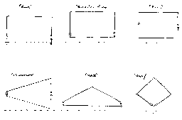
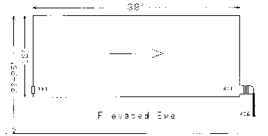
The 'Ewe' (Fig. 2, top left), perhaps the best well-known of the genre after being introduced by Floyd Koontz in 'QST' magazine, can be considered exactly half that loop, using ground as the divider and return. Fig.2, top middle is an elevated Ewe, wire replacing the ground return. The 'imbalance' of termination and feedpoint hardly affects the theoretically available cardioid pattern at all. Indeed the K9AY (Fig.2, bottom right) brings the termination and feedpoint right together, (dramatically easing direction switching etc.) but does demand a ground or plane at that point as a potentiometric separator. Again, near identical cardioid. Same with the 'Flag' and 'Pennant' (owing to Earl Cunningham, K6SE), the 'Kaz' (Neil Kazaross, a prominent medium-wave DXer) and pretty much every other elevated terminated loop (ETL).
The many and various designs have next to nothing to choose between them for pattern (do I have to say 'cardioid' even once more?) but play variously to ease of installation, size, ready direction switching, and/or relatively constant impedance and/or accurate tracking of nulls over broad bandwidth. As for the last two, it is of little consequence what the antenna 'looks like' to the receiver, the 'broadband' designs hold their patterns little better than any of the other designs, and those with theoretically deeper or wider nulls tend to wash out in the real world, particularly if the terminations are not carefully trimmed. They all differ in (very) minor response detail, since none of them are infinitesimally small in wavelength. Again, although tidy minds might rebel at the seeming asymmetry of the 'Elevated Ewe', Fig.2 top centre, versus the 'Flag' (Fig.2, top right) there is in neither modelling nor measuring anything of difference worth mentioning. However, the 'Elevated Ewe' is considerably easier to erect and maintain.
|
Their one major strength is the potentially relatively deep null off the rear; the trick with these simple antennas is not to point them AT things one wants, but point them directly AWAY from things one doesn't.
A raw cardioid pattern, consisting of a very broad frontal lobe and a sharply defined narrow null off the rear, is pretty weedy unless one can point that null at something obnoxious. In the northeast US, ETLs with their nulls aimed towards 'static alley', Texas to Florida, prove useful. That as a consequence they end up sort-of pointing at Europe is handy, but unimportant; it's the suppressing the storm-noise that counts.
|
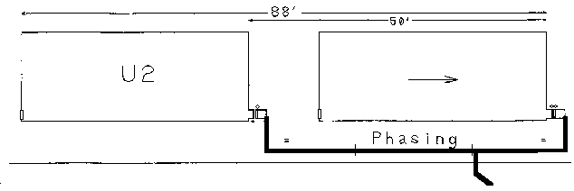
Terminated Loops only get really interesting though when combined in arrays; these can be 'in-line' (i.e. one in front of the other) or 'broadside', side-by-side. Optimum spacing for side-by-side on, say, topband tends to be too wide for eighty, with the 'nose' fracturing into lobes; optimum for eighty is inadequate for topband with barely improved directivity over a single antenna, so one of the big plusses - the broadband nature of the antenna - goes away. Additionally the space required - say 300 feet separation for topband - is starting to veer dangerously back towards Beverage-land.
In-line arrays can be made to track broadband much better, easily well enough over say the octave encompassing topband and eighty, but at the cost of some sensitivity, meaning non-miniature loops and preamplifiers are necessary.
|
|
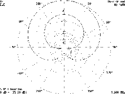
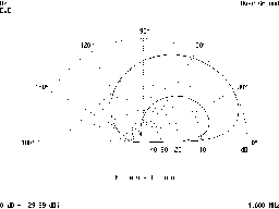
So what has been the purpose of this minor exposition on terminated loop antennas? One of these 'U2' arrays, and a couple of conventional single terminated loops, were targets for the measurement technique described later. Mostly because I wanted to see if they worked as advertised (modelled), or whether I'd been fooling myself with them for the last few years!
Introduction / Summary
Section (1) . . *** Receive Antennas ***
Section (2) . . Signals, and Signal Processing
Section (3) . . Measuring
Section (4) . . Problems and Solutions
Home
© Steve Dove, W3EEE, 2003