| Evaluating Receive Antennas with a Soundcard |
Introduction / Summary
Section (1) . . Receive Antennas
Section (2) . . Signals, and Signal Processing
Section (3) . . Measuring
Section (4) . . *** Problems and Solutions ***
What goes wrong?
Why do some people have good luck with these antennas, and others disparage them? Sadly, really good performing ones seem rare - Why?
* Starry Eyes . . Unreal or excessive expectations
Some folk chuck a piece of wire in the air and think they've got some kind of death-ray. Even when working properly, a cardioid response is just a cardioid response. It is comparable to a two-element driven array. The only thing of directional significance is that reasonably deep null off the back - it is a one-trick pony. Frankly, nothing else has much real effect in the real world; the few dB attenuation off the sides is barely noticable in battle. It takes a properly working array of ETLs to approach the performance 'expected' from a casual glance at the azimuth response of a single loop.
* Incorrect termination
The termination resistor value MUST be trimmed in situ. It is critical. Just plonking in the 'book' or model value almost guarantees throwing away many dB of null depth, the major strength of the antenna. It is easy to do, makes so much difference, and so few do it. Cringe. I have a fairly local AM station at the high end of the band 'off-the-back' of euro-facing antennas; listening to that on a portable radio attached to the antenna, I tweak a 2kohm 10-turn pot at the termination until it nulls most.
* Insufficient feedline isolation
In addition to presenting the feedline with a suitable source impedance, the 'matching' transformer should serve to isolate the feedline from the antenna. Some do a good job, others don't. Ideally, the feedline should be dropped straight down to a decent ground connection, then a line isolator, or enough ferrite on the feedline to provide a high common-mode impedance, added before the run back to the shack, where connection is made through another transformer (to obviate ground loops). (Lest decoupling is considered fru-fru, try modelling the antenna with a random bit of wire connected to one side or the other of the feedpoint and see what happens.) Not insignificantly, any garbage picked up on the feedline as common-mode will get correspondingly turned into differential mode by the same mechanism and become inseparable from the desired signals. This is a prime method for entry of the 'squirglies'.
* Noises . . Noise coupling:
They are sensitive to nearby or crossing power-line noise. Distance is the only cure. Feedline common-mode exacerbates this, often dominates, and needs to be fixed first..
* Conductor pollution:
The biggy. These small loops are highly sensitive to 'conductor pollution', i.e. the effect of nearby wires or metal structures of any sort. These can and do warp the true cardioid response, typically degenerating that hard-won rear null. At worst, a nearby (meaning as close as 1/4 wavelength away) resonant antenna at the frequency of interest can completely destroy any hope of directionality.
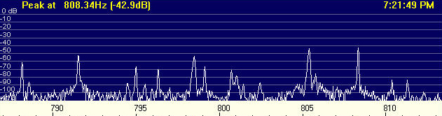
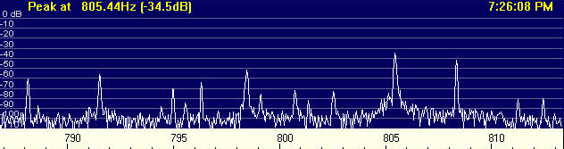
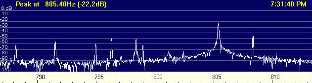
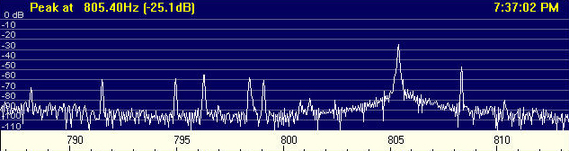
As it just so happens, partly to illustrate this point, and partly because I needed yet another antenna, I installed a 'Mondo-Kaz', a single triangular loop some 40m long and 10m high in the centre with the 'live' end about 20m away from a 160m vertical, self-resonant at 1.7MHz. Here, Figs. 16,17,18 and 19 illustrate the effect of proximity. They are of nominal 1600kHz with a 'local' station (at 805.5) pretty much bang in the null behind - yes, in fact it is the signal I use to trim termination resistors - and conveniently, a signal 'on-the-nose' for reference (at 808.5). The 'Kaz' has been trimmed, to the tune of some 22dB rear rejection of the 'local'.
Section (1) . . Receive Antennas
Section (2) . . Signals, and Signal Processing
Section (3) . . Measuring
Section (4) . . *** Problems and Solutions ***
Introduction / Summary
Home
© Steve Dove, W3EEE, 2003